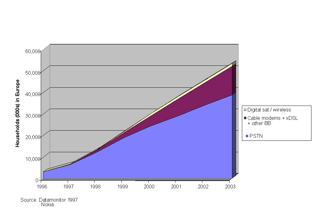
Fig. 1: Residential Internet usage in Europe
September 28rd, 1998
Heikki Almay
Electrical and Communications Engineering
Helsinki University of Technology
Heikki.Almay@ntc.nokia.com
Risto Mononen
Electrical and Communications Engineering
Helsinki University of Technology
Risto.Mononen@ntc.nokia.com
Kari Melkko
Laboratory of Telecommunication Software and Multimedia
Helsinki University of Technology
Kari.Melkko@ntc.nokia.com
Aim of this paper is to present some network technologies that IP is transported on. Remote access, Local Area Network and Internet Backbone protocols are included.
This document describes the use of IP over different networks. The intention is to give the reader a clear understanding of the different situations where IP is used over other network technologies.
The application areas covered are remote access, LAN access and the IP backbone.
For each of the three application areas the basic needs and principles that arise from the applications are outlined. Example network configurations are shown and an overview of the protocols and specifications used are given. Additionally implementation related issues of these technologies are discussed.
IP can be carried over ATM, DTM, Ethernet, FDDI, Frame Relay, GSM, ISDN, PDH, PSTN, SDH/SONET, Token Ring, UMTS and WDM networks and many more. As the number of network technologies being used for carrying IP is extremely high, only a selection of the most important is discussed.
The basic need for remote IP access is the desire to connect users temporarily to an IP network. The technology is also called 'Dial-in Access'. It is used when the use does not justify costly direct IP access or when the user is mobile.
The technology has been developed for accessing IP networks over the PSTN but the same mechanisms apply for ISDN and ADSL access as well as other technologies.
The most widely known application today for remote IP access is residential
users accessing "the Internet" - or actually an ISP network.
The immense growth of residential Internet use is shown in fig. 1. 
Fig. 1: Residential Internet usage in Europe
The second killer application is remote work where employees connect
to the corporate network from their home office. Gartner Group /3/ estimates
the number of remote workers to reach 100 millions year 2002 (See fig.
2). The growth in remote working and the different types of remote workers
are outlined in fig. 2 below. 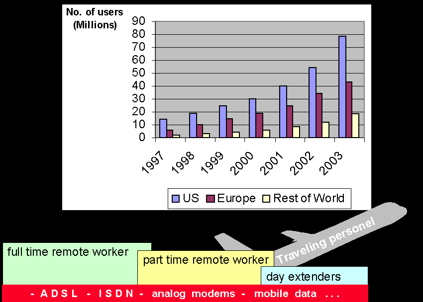
Fig. 2: Remote work
Affordable remote IP access is one of the key enablers for remote work. It is likely that all major remote access technologies available will be used for remote work. Full time remote workers who totally rely on their home office have been early users of ISDN. They are also likely to adopt ADSL early. For part time remote workers and day extenders the network connection is not mission critical. It will take longer time for these groups to switch to new costly technologies. Traveling personel are a key target group for mobile data.
In addition to Internet and remote work a third major application of remote IP access is connecting small branch offices to the corporate networks.
Remote IP access is a relatively new issue in the Internet community. The all relevant specifications have been made in the 1990's.
From the applications a number of special requirements arise.
In this chapter the network configurations and protocols used to meet the special needs of remote IP access are discussed. The main focus is on connecting remote users to IP access servers, but the intention is to give the reader the understanding of how state of the art remote access is performed in the complex network environment where different organisations and networks are involved.
The configurations for remote IP access over the ISDN/PSTN network and over ADSL access are discussed. From the 'IP point of view' remote access over other technologies, such as cable modems looks quite similar.
In the ISDN/PSTN the increasing remote IP access brings up some interesting questions regarding network dimensioning and further development. These are briefly outlined.
Network overview
In fig. 3 below an overview of the systems used for remote IP access
over ISDN/PSTN is shown. In the example the IP access is provided by the
network operator. Today it is however still very common that companies
and ISP's have their own access servers or modem pools. 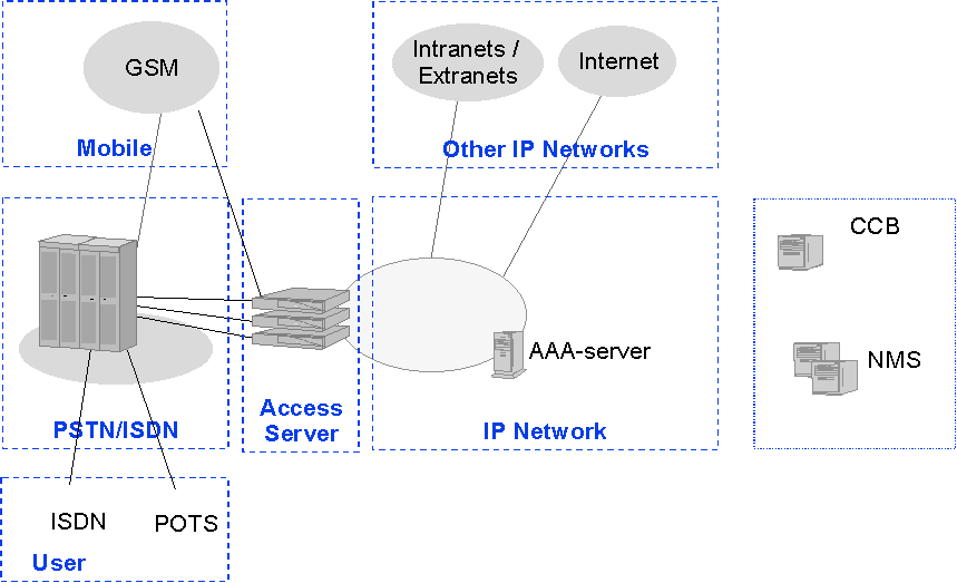
Fig. 3: IP access configuration for ISDN/PSTN (network operator
provides IP access)
In fig. 3 the users are connected by ISDN or analog modem connections to the access server. GSM data is converted in the mobile switching center either to a modem signal or mapped according to V.110. The connections between the telephone exchange and the access server is typically ISDN primary rate access (2Mbps).
The access server includes modem pool and router functionality. The PPP-protocol [discussed later] is in most cases terminated in the access server. For authorization and authentication and accounting the AAA server is used. The access server and AAA-server communicate using e.g. the RADIUS-protocol.
From the access server the user data is routed as IP packets towards its destination. The support systems NMS (network management system) and CCB (customer care and billing system) are essential for the smooth operation of the system and for efficient service provisioning, but they are beyond the scope of this document.
Functionally remote IP access over ADSL shown in fig. 4 is very similar
to the ISDN/PSTN case. In stead of access servers a combination of Digital
Subscriber Line Access Multiplexers (DSLAM) and Remote Access Nodes (RAN)
is used. The DSLAM contains the ADSL line cards. The traffic over the ADSL
line is e.g. PPP over ATM . The DSLAM also acts as a concentrator for the
subscriber traffic. If ATM is used on the ADSL line, it is easiest to do
the traffic concentration also on the ATM layer and use ATM for connecting
the DSLAM with the RAN. In the RAN the PPP sessions are terminated. 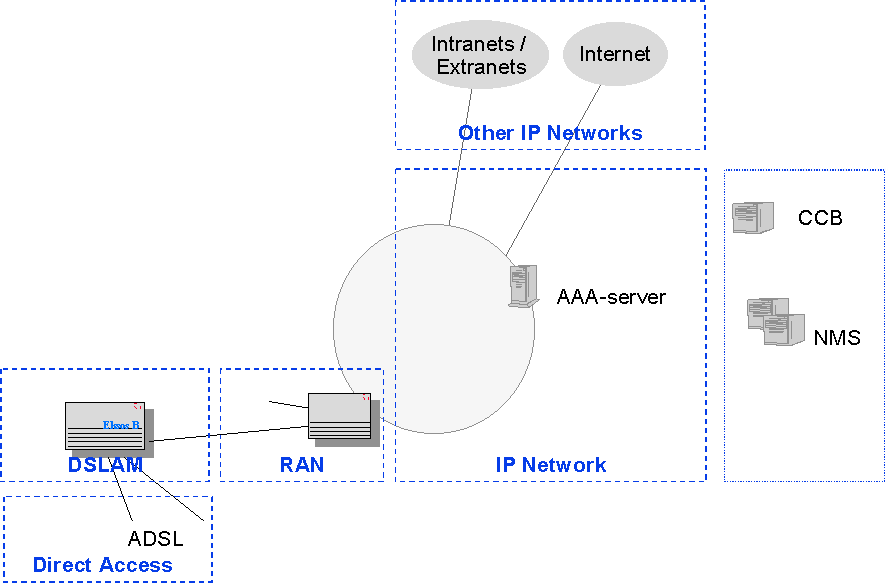
Fig. 4: IP access configuration for ADSL (network operator provides IP
access)
Note that from an architectural point of view the only difference between the ADSL access and the ISDN/PSTN case is, that the in the latter the modem functions and the RAN have been combined to one physical device. In ISDN/PSTN data calls can be carried over vast distances in digital form. The optimization criteria is often the tariff area. For ADSL the physical length of the modem connections is limited, which means that initially when the ADSL subscriber density is low, it makes sense to use small simple devices that are distributed throughout the access network.
Customer premises equipment
Typically the end user device to be connected to the network is a PC. Also small LAN's can be connected.
The CPE (customer premises equipment) for ISDN/PSTN include
In the figure below example ISDN CPE configurations are shown.
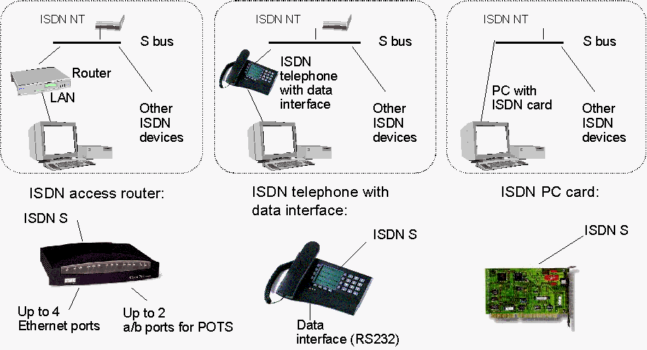
Fig. 5: Example ISDN CPE
configurations
While the different types of CPE basically support the same service, they are used for different purposes. Modems, ISDN PC cards and terminal adapters are typically used by single users. With all these devices connections can easily be made to different IP-networks by just selecting connection profiles from the PC (login name, password, telephone number, used protocols etc.).
SOHO routers support several simultaneous users, but they are more rigid. The used telephone numbers and the routers IP address are typically configured when the system is taken into use. When the router receives packets that have to be sent to the ISDN port it sets up the connection to the pre-defined destination. Connecting to a different telephone number or just a different IP network requires a new router configuration. This is a challenging task for normal users.
For ADSL routers, bridges or modems are used as CPE. The typical PC-interface is Ethernet. On the ADSL-connection some implementations use ATM to carry the PPP traffic, some rely on PPP only.
Access Server
In stead of dedicated modem pools and attached routers universal access servers are increasingly used for remote IP access. These devices perform following functions
- modem protocols
- ISDN
- rate adaptation protocols
- compression protocols
- access lists
- support for authentication, authorization, and accounting (e.g. RADIUS
protocol)
- level two tunneling
In ADSL access the RAN performs all the PPP-related functions, security enforcement and routing.
AAA-server
The AAA-server performs authentication, authorization and accounting, i.e. it checks if the user is known and allowed to set up the connection he requests and collects information on the connection duration and transferred amount of data.
Authentication and authorization information is stored in a database. Usually the user information is the login name and password.
There are also ways for an AAA-server to assist in connecting the user to an other IP network. In this case the domain name is the relevant user information. This functionality can be used when an ISDN/PSTN operator is offering IP access services for corporates and ISP's. For corporate users the AAA-server can initiate a level two tunneling connection.
In case of ISP selection the AAA-server can forward the user information to the AAA-server of the target network where it is checked. This is done using the RADIUS proxy functionality.
Example network configurations for the AAA-server "Nokia Artus
Access Manager" are given in the figures below. Fig. 6 shows how an
ISDN/PSTN operator configures the AAA-server for serving corporate access
(e.g. remote work). Here the AAA-server is used for initializing tunneling
connections and for collecting data for charging purposes. 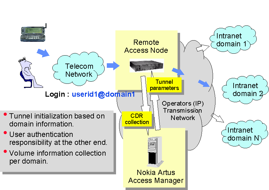 Fig 6: Example configuration for a network operator
In fig. 6 below the AAA-server is used by an ISP for authentication
and authorization of the users and for collecting information for charging
purposes. 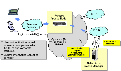
Fig 7: Example
configuration for an ISP
PPP
The Point-to-point protocol provides a standard method for transmitting datagrams using serial point-to-point links. PPP is comprised of three main components:
1. A method for encapsulating datagrams over serial links.
2. A Link Control Protocol (LCP) for establishing, configuring, and testing the data-link connection.
3. A family of Network Control Protocols (NCP's) for establishing and configuring different network-layer protocols.
Points 1. And 2. are covered by RFC 1661.
The PPP protocol was first introduced as late as 1992. Until then relatively few users had been connected to the Internet by point-to-point connections. Non-standard mappings were used. The de facto standard was SLIP, Serial Line IP (RFC 1055), which is a very simple packet framing protocol.
The PPP protocol has four phases: Link Establishment, Authentication, Network-Layer Protocol and Link Termination.
The Point-to-Point Protocol is more than an encapsulation scheme. It provides a Link Control Protocol (LCP) that can handle a variety of options (e.g. limits of packet size). Issues related to network protocols are handled by a family of Network Control Protocols. These protocols are available for a wide variety of network-layer protocols. Some examples:
- The PPP Internet Protocol Control Protocol RFC 1332
- The PPP OSI Network Layer Control Protocol RFC 1377
- The PPP Internetworking Packet Exchange Control Protocol RFC 1552
The PPP frame format is shown in fig. 8 below.
+----------+----------+----------+----------+------------

|   Flag   | Address  | Control  | Protocol | Information

| 01111110 | 11111111 | 00000011 | 16 bits  |      *

+----------+----------+----------+----------+------------

              ---+----------+----------+-----------------

                 |   FCS    |   Flag   | Inter-frame Fill

                 | 16 bits  | 01111110 | or next Address

              ---+----------+----------+-----------------
Fig 8: PPP frame format
As seen from the frame format in addition to the user information only the protocol field is variable. This field provides for multiplexing of different network-layer protocols simultaneously over the same link.
Protocols assigned include the following
Value (in hex) Protocol Name

0021 Internet Protocol

0023 OSI Network Layer

002b Novell IPX

8021 Internet Protocol Control Protocol

c021 Link Control Protocol

c023 Password Authentication Protocol

c025 Link Quality Report

c223 Challenge Handshake Authentication Protocol
PPP over various networks
PPP was originally designed mainly for short haul serial connections
and dial-in connections over the PSTN. Since then PPP has also been introduced
to a wide variety of other environments, e.g.
| PPP over ISDN | RFC 1618 |
| PPP over SONET/SDH | RFC 1619 |
| PPP in X.25 | RFC 1598 |
| PPP in Frame Relay | RFC 1973 |
The main issues discussed in these RFC's are encoding, framing, and link control protocol options.
PPP Multilink protocol
The need for 'bandwidth on demand' and n x 64kbit/s data connections have brought up several solutions for using multiple PPP-connections for one network layer connection. The most widely accepted solution is PPP Multlink protocol (RFC 1990). The technology is most commonly used for setting up 128 kbit/s ISDN connections, but it can also be used e.g. for complementing a leased line with a dial-up connection when extra capacity is needed.
The PPP Multilink protocol essentially consists of the definition of a multilink header for sequencing and fragmenting of frames and extensions to the PPP Link Control Protocol which allow the multiple bundled links to be set up and closed on demand.
PAP
The Password Authentication Protocol (PAP) is described in RFC 1334. It provides a simple method for the peer to establish its identity using a 2-way handshake. This is done only upon initial link establishment. After the Link Establishment phase is complete, an Id/Password pair is repeatedly sent by the peer to the authenticator until authentication is acknowledged or the connection is terminated. PAP is not a strong authentication method. /RFC 1334/
CHAP
The Challenge-Handshake Authentication Protocol (CHAP) is used to periodically verify the identity of the peer using a 3-way handshake. This is done upon initial link establishment, and may be repeated anytime after the link has been established. /RFC 1994/
RADIUS
The Remote Authentication Dial In User Service (RADIUS) is defined in RFC 2138.
Security, authorization and accounting for a large number of users can be best achieved by managing a single database, which allows for the verifying of the user name and password as well as configuration information detailing the type of service to deliver to the user (for example, SLIP, PPP, telnet, rlogin).
A [Network] access server operates as a client of RADIUS. The client is responsible for passing user information to designated RADIUS servers, and then acting on the response which is returned. RADIUS servers are responsible for receiving user connection requests, authenticating the user, and then returning all configuration information necessary for the client to deliver service to the user.
A RADIUS server can act as a proxy client to other RADIUS servers.
Transactions between the client and RADIUS server are authenticated through the use of a shared secret (password), which is never sent over the network. User passwords are sent encrypted.
The RADIUS server can support a variety of methods to authenticate a user. When it is provided with the user name and original password given by the user, it can support PPP PAP or CHAP, UNIX login, and other authentication mechanisms.
Tunneling and L2TP
When users connect to corporate networks using public IP access, level two tunneling through the IP network can be used for enhanced security. In the tunnel connecetion a PPP datagram (containing IP packets) is encapsulated and sent as such to the corporate network. As a result the IP addresses included in the original IP header are not used for routing. They are part of the payload. This makes it difficult for externals to determine the structure of the corporate network.
The Internet draft Layer Two Tunneling Protocol "L2TP" defines a tunneled connection between an L2TP Access Concentrator and an L2TP Network Server. In the network examples discussed the Access Concentrator equals the network operators access server or RAN. The Network Server equals an access server or RAN in the corporate network.
A tunnel carries PPP datagrams between the tunnel end points. Many sessions can be multiplexed over a single tunnel. A control connection operating in-band over the same tunnel controls the establishment, release, and maintenance of sessions and of the tunnel itself./L2TP/
L2TP uses UDP. The entire L2TP packet, including payload and L2TP header, is sent within a UDP datagram.
L2TP is peresented here as an example, as it is likely to become a widely accepted standard. At the moment proprietary solutions are used.
Modem protocols and other relevant ISDN/PSTN issues
Just ten years ago typical analogue modem speeds ranged from 1200 bps to 9800 bps. Today 33600 bps and 56000 bps are shipped. First generation ISDN devices (terminal adapters) used V.110 rate adaptation. Today PPP over ISDN and sometimes V.120 rate adaptation are used. In addition to faster modem protocols and enhanced rate adaptation protocols, error correction and compression has been introduced.
As a result of the fast development ISP's and other organisations that cannot control the CPE used for accessing their IP network have to support a wide varitey of different protocols. Practical implementations do not support all protocols and combinations of protocols. Below an implementation example is given.
Implementation example:
Modem ISDN Channel Aggregation Specifications for Cisco AS5200/AS5300
Access Servers

Rockwell K56flex at 56000 to 32000 in 2000 bps increments

- ITU V.90 56K (Q2 1998)

- ITU-T V.34 Annex 12 at 33600 and 31200 bps

- ITU-T V.34 at 28800, 26400, 24000, 21600, 19200, 16800, 14400, 12000,
                9600, 7200, 4800, and 2400 bps

- ITU-T V.32terbo at 19,200, 16,800, 14400, 12000, 9600, 7200, and 4800 bps

- ITU-T V.32bis at 14400, 12000, 9600, 7200, and 4800 bps

- ITU-T V.32 at 9600 and 4800 bps

- ITU-T V.23 1200/75 bps (back channel)

- ITU-T V.22bis at 2400 and 1200 bps

- ITU-T V.22 at 1200 bps

- ITU-T V.21 at 300 bps

- Bell 212A at 1200 bps

- Bell 103A at 300 bps

Error correction:

- ITU-T V.42 (including MNP 2-4 and LAPM)

Data compression:

- ITU-T V.42bis (1K nodes) and MNP 5
For meeting the needs of a typical corporate IT policy, end-to-end security has to be engineered on top of the basic remote IP access solution. In practice this means data encryption and strong authentication e.g. with one time passwords.
Here a good solution is at the moment not in sight and practical problems make it difficult to implement secure systems that are acceptable for the users. Legislation is also lagging behind. In some countries the use of strong encryption is forbidden. US export regulations have until now forbidden the export of products incorporating strong cryptography.The growing use of remote IP access has some impact on the PSTN network.
The traffic generated by the Internet users is different from the traditional
voice traffic /2/. Calls to IP networks can result in
- long calls (30 min typical for Helsinki)
- short calls (single transactions)
- a high rate of unsuccessfull calls (when access servers are congested)
- correlated traffic
As the traffic profiles depend on the applications used, they are constantly changing. Web-browsing is a good example of a relatively new service, that has lead to long holding times. Content push may again change the picture. The only thing that is sure is, that the old theories used for teletraffic engineering do not apply.
In the figure below an example is given about the potential impacts
of IP remote access traffic to the PSTN. It is assumed the of a population
of 50 000 subscribers 10% start using remote access in addition to their
current traffic. It is assumed that during busy hour they generate 200mErl
new traffic. 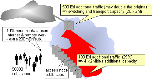
Fig. 9: PSTN
dimensioning
In the example it is actually assumed that a large portion of the remote access users are teleworkers as they generate much traffic at the busy hour which is during office hours. Peak traffic for residential IP access is typically in the evening (e.g. 21.00 - 22.00).
The traffic increase in the access network is 25%, which typically can be handled with the existing systems e.g. by adding trunks between concentrator and switch or by switching heavy users to separate multiplexers. However the increased load of the access network has led to the development of data call bypassing solutions. In these solutions the data calls are directed to an access server without going through the telephone exchange. Data call bypassing is a theme especially in the US, where flat rate tariffs for local calls contribute to long call holding times.
An other interesting phenomena is the concentration of IP-access traffic to specific points in the telephone networks. These can be switches connected to large ISP's or gateways to other networks to which the ISP's are connected. In the example it is assumed that half of the traffic is carried to the network of an other operator. E.g. in Sweden Tele2 is the biggest ISP. They have only very few direct customers. At these hot spots the change in traffic may be significant. In the example it is assumed that 50% of the IP remote access traffic goes to an other network.
The dimensioning of the IP access resources is one questions for practical implementation. The simple reason is, that the access servers are by far the most expensive part of the network. The price tag for one 64kbps is above USD 500. ISP's with high quality of service dimension currently roughly one port per 10 subscribers. For ISP's with mainly residential subscribers the ratio can even be 1/20. With this kind of dimensioning the expensive access servers are well utilized, but the averse effects on the perceived quality of service are obvious. For January 1998 A&T WorldNet Service reported that their service outperformed the industry average on the ability. The users were able to connect 95.4% on the first try. During evening peak hours the figure was 92.3%. From the PSTN point of view 7.7% of the busy hour call attempts were unsuccessful.
The vast majority of the Internet users are still connected to campus or corporate LANs.
The most favored network technology used is Ethernet, which originates from early 70's. Ethernet requires decent cabling and additional equipment that has limited LAN access possibilities. Nowadays, households can be connected to LANs too by using Cable Modems that utilize existing cable television network for data transmission. Among with cable modems, wireless LAN technology provides new infrastructure that can be used in environment where traditional LAN equipment cannot be installed. These LAN technologies will be discussed in this presentation.
Other LAN technologies include Token Ring and Token Bus, FDDI and ATM
LANE. Token Ring and -Bus are network technologies intended for Ethernet-like
use. They are more sophisticated, complex and more expensive than Ethernet.
Although Token controlled networks provide better performance than simple
Ethernet, they have never become popular. FDDI was mainly used in LAN core,
but nowadays ATM and gigabit Ethernet have replaced it. ATM LANE and other
IP over ATM applications are out of scope of this presentation.
Ethernet is a network technology that utilizes shared media, originally
thick 0.5" coaxial cable (coax). Nowadays Ethernet operates on almost
any media - thin 0.25" coax, twisted pair, multi-mode fiber and mono-mode
fiber. Also Ethernet network topology is versatile. Star and hub/tree topologies
are used among simple bus. Ethernet utilizes IEEE 802.3 specifications
that define physical layer.
The defined physical layer alternatives are [LMAN]:
10BASE5 is the original 802.3 medium setup. It consists of thick, 0.5" coax bus with a transceiver at the cable tapping point known as attachment unit interface (AUI), and additional cabling, know as drop cable, between the host and the transceiver. Both ends of the coax bus are terminated with a resistor that has resistance equal to the actual cable. Max. length of the bus is 500 meters [DACO].
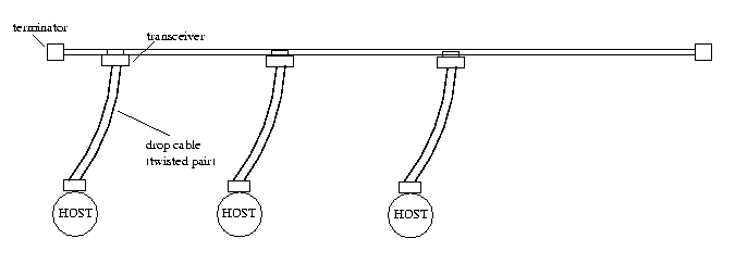
Figure 3.1 Ethernet thick coax bus topology.
Arrangement illustrated above is not very cost effective since additional equipment and cabling is required. Besides it is not fault tolerant: A broken cable tapping point or malicious host permits normal operation of the whole network segment.
Similar solution is to use thin 0.25" coax instead of thick coax.
Hosts are connected directly to the thin coax bus that can be max. 200
meters long [DACO]. Also with this 10BASE2 arrangement, network is susceptible
to any faults in the cable or hosts' network equipment.

Figure 3.2 Ethernet thin coax bus topology.
At present most popular design in Ethernet LANs is to connect hosts with
10BASE-T twisted pair cable to a device called Hub. Hubs have several ports
for the hosts and a connection to the network framework. Simple hub is
just a repeater that broadcasts the traffic from any port to rest of the
ports + the network framework and vice versa.
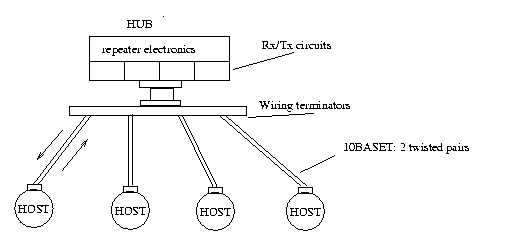
Figure 3.3 Ethernet hub topology
10BASE-F fibers are especially used between hubs and LAN core. Point-to-point
connections up to 2 km are possible. When fibers are used, a pair for each
link is needed - a fiber for transmission and another for receiving. 10BASE-F
also defines a star topology for fibers - up to 33 stations can be attached
to a central passive star that distributes traffic from any station to
all the other stations. Max link length in this configuration is 1 km.
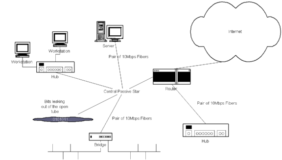
Figure 3.4 Ethernet topology with fiber links.
Ethernet is connectionless, frame exchange protocol. Each Ethernet station
has unique, 6 octet long address and it may send and receive max. 1518
octet long frames to/from any station attached to the same network. Minimum
length of the frame is 512 bits. If size of actual data transmitted is
less than 38 octets, PAD bits are inserted to the frame. Preamble
is a bit pattern that is sent as a start of the frame delimiter. CRC is
32-bit Cyclic Redundancy Check value that ensures that corrupted frames
are detected.
+-----------+------+-------------------+---------------+---------+-----------+---+-------+
|Preamble(7)|SFD(1)|Destination addr(6)|Source addr (6)|Length(2)|Data(<1500)|Pad|CRC(4)
|
+-----------+------+-------------------+---------------+---------+-----------+---+-------+
Figure 3.5 Ethernet frame format| .
Ethernet frame consists of the following fields:
RFC 894 defines how IP header and data is inserted in LLC data field;
Type field contains the value hexadecimal 0800, immediately followed by
IP header and/or data.
Any network protocol that operates on shared media requires Medium Access Control (MAC). IEEE 802.3 defines CSMA/CD (Carrier Sense Multiple Access / Carrier Detection) protocol that is used in Ethernet networks.
CSMA/CD algorithm is fairly simple: Whenever station wants to transmit data, it first listens the media. If someone else is transmitting, station will wait until media is free. Once the media is free, station waits a short interframe gap time and starts transmitting. While transmitting data, the station simultaneously monitors received signal to detect if some other station has started transmission too and thus corrupting the frame. If two stations transmit simultaneously, a collision occurs. In this case, both stations stop transmission of the frame, and transmit a jam sequence to the network to ensure that all other stations detect the collision. Station that failed to transmit the frame, increases frame attempt limit counter and checks if attempt limit is reached. If limit permits to continue frame computes random backoff time, waits and starts listening the media, thus re-starting the algorithm.
Minimum length of the Ethernet packet and maximum link length definitions
arise from the fact that hosts located at the opposite ends of the same
segment must be able to detect collision when both send shortest defined
frame.
The simplest possible LAN architecture is to use 10BASE2 bus. Each station
connects to shared cable that has maximum length of 200 meters. However,
this kind of Ethernet LAN is not usable except in very small test networks.
Larger networks would be possible by connecting several segments, e.g.
buses with hosts attached, together.
Bridge is a device that is used to interconnect several LAN segments.
It is connected to each segment with normal Ethernet interface and it passes
traffic from any segment to other segments. As identical MAC protocols
(IEE 802.2) are used in each segment, processing power needed in the bridge
is minimal. Usually bridges are somewhat brighter than required for basic
operation. Learning bridges have tables for each segment and by listening
the traffic they fill the tables - if destination address is found from
the table, frame is passed only to the segment where the destination station
is located. A frame containing destination address not found from the table
is broadcasted to every segment except to the one that sent it. Bridges
are used in LANs for various reasons:
Since bridges process Ethernet frames without modifying them, bridge is a transparent layer-2 device.
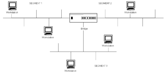
Figure 3.6 Ethernet LAN with three segments and a bridge.
Previous installation utilized 10BASE2 coaxial cable as a bus where stations connect. However coax has many weaknesses as pointed in section 3.1.1 and therefore all recent Ethernet installations use twisted-pair wiring with hubs. Passive hub simply cross-connects transmit cable pair from every port to receive cable pair of each port.
Modern hubs include enhanced security options so that they deliver actual frame only to the correct port and send scrambled noise to other ports. State-of-the art hubs perform Ethernet switching, which increases network efficiency significantly.

Figure 3.7 Ethernet LAN with hubs.
By increasing the complexity of the hub electronics, a hub can operate like a learning bridge. By listening network traffic hub builds a routing table that contains the MAC addresses of the stations at each port. Once table is created, frames from any port are transmitted only to the ports they are addressed. If destination address is not found, frame is transmitted to the next hub in network hierarchy. Switching hubs include a FIFO-buffered backblane bus line so that the hub is able to transmit several frames through the hub concurrently. Usually switching hubs support dual speed operation - some ports may operate in 10Mbps mode, while others are 100Mbps or 1Gbps. By connecting 100Mbps port to LAN core and configuring other ports to operate in 10Mbps mode, each station has dedicated 10Mbps bandwidth. [DACO]
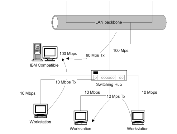
Figure 3.8 Switching hub.
In addition to switching hubs, Ethernet switches (or simply Switches) are used increasingly in Ethernet LAN core to replace routers. This produces flat LAN topology, but as switching is much faster than routing, decreases packet propagation delays thus increasing LAN bandwidth.
Modern routing Switches are devices that combine functionality of a traditional router and a switching hub. If destination MAC is known, frame is switched through the Switch to the destination. If destination is unknown, frame is delivered to a router part of the device, which processes IP packets. See [BRSW] for more information.
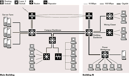
Figure 3.9 Ethernet LAN equipped with Switching hubs and Routing Switches.
Traditional cable TV networks carry a band extending from about 50 to a few hundred megahertz. The network topology is essentially a tree, distributing the television signal from a central site's headend to the subscribers' cable drops. Intermediate amplifiers are needed along the way to ensure an adequate signal level at the customers' homes. The current trend is to convert the backbone network infrastructure to fibre optic cables and digital transmission.
Each TV channel occupies a band of some 6MHz. Cable modems will typically be allocated the band of one TV channel on the network for the transfer of data from the cable operator's central site to customers. Cable modems thus interfere in no way with normal television viewing on other channels. [DACO]
The data communications network will use some or all parts of the cable TV network as its transmission paths. Structurally, it will be composed of a number of broadcast segments connected together and to the Internet by a backbone network. This entails that the 6MHz bandwidth is shared by all users on the same segment, which could be hundreds or even thousands altogether. The backbone network for data communications could consist of one or more 6MHz channels on the cable TV backbone network. The cable operator can always control the amount of traffic on a segment by limiting the number of customers on the segment.
IEEE 802.14 Committee is in process to create standards for CATV equipment.
Wireless LANs can be used as an extension in LAN. A wireless LAN saves
the cost of the installation of LAN cabling and eases the task of relocation
and other modifications to network structure [LMAN]. Simplest single-cell
wireless LAN consists of a Control Module (CM) that is connected to a wired
Ethernet segment and acts as an interface to a wireless LAN. CM includes
either bridge or router functionality to link the wireless hosts to Ethernet
backbone. In addition, it includes access control logic, which regulates
the access from the wireless hosts.
Few wireless technologies exist:
Physical mediums are specified in IEEE 802.11 standard which also specifies
Ethernet-like distributed foundation wireless MAC (DFWMAC).
Underlying LAN technology is not aware of what network-level protocol
is used on it. It only processes and transfers frames that have network
technology specific MAC addresses. Network level protocol, such as IP,
is only transparent data. Address Resolution Protocols are needed to integrate
Layer 3 addressing to underlying MAC addressing.
[RFC826] defines ARP protocol to be used with Ethernet. It is assumed that host knows its own IP address and netmask.
Before sending an IP packet, sender determines if packet destination is located in the same LAN by comparing N first bits of own IP-address and destination address. If bits match, destination is located in the same network and it should be delivered directly utilizing MAC addressing. If destination is outside the local subnet, IP-packet must be passed to the default gateway (router) of the subnet that delivers packet further. In both cases, MAC address of the frame receiver must be resolved.
Each host in Ethernet LAN has local routing table that ARP maintains. Table includes IP-MAC address pairs of the hosts connected to same subnet with which the host communates. Unless used, an address-pair is removed from the table after a certain time limit. If host is just connected to the network or it has been idle the table is empty.
ARP solves MAC address by sending an Ethernet frame that carries ARP request message. Frame is targeted to all hosts in the network by using broadcast MAC address as destination. ARP request contains
Each host in the network checks if ARP-request contains its IP-address. If addresses match, host first adds source IP-MAC address pair in its own routing table and then sends ARP reply message to the source. ARP reply contains IP-MAC address pair of the host and it is targeted to MAC address found from ARP request message.
Host that sent ARP request receives ARP reply, adds IP-MAC address pair
in local routing table and sends Layer 3 packets to the destination using
resolved MAC address.
Reverse ARP is used when a diskless station that is not aware of its
own IP address is connected to the network. The server associated with
the diskless host has a table of IP-MAC address pairs. When diskless station
is booted, it broadcasts an reverse ARP request to the network. Request
contains MAC address of the station. As RARP server receives the request
it checks if its RARP table contains IP-address for this MAC-address. If
IP-address is found RARP reply containing IP-MAC address pair of the server
and station is sent back to the diskless station.
1
8 9
16
- - - - - - - - - - - - - - - - -
| Hardware type
|
---------------------------------
| Protocol type
|
-------------------------------
| HLEN | PLEN
| HLEN = Hardware addr. length
--------------------------------- PLEN = IP address length
| operation
| operation = 1 ARP request
---------------------------------
2 ARP response
| Sender
|
3 RARP request
-
-
4 RARP response
| Hardware
|
-
-
| Address
|
---------------------------------
| Sender
|
-
-
| IP-address
|
---------------------------------
| Target
|
-
-
| Hardware
|
-
-
| Address
|
---------------------------------
| Target
|
-
-
| IP-address
|
---------------------------------
Figure 3.10 (R)ARP message format.
The operation field of the message specifies message type: ARP request/reply
or RARP request/reply. Hardware type is set to 1 in CSMA/CD networks. Protocol
type is either ARP or RARP.
Dynamic Host Configuration Protocol [rfc1531] is used for similar
operation as RARP. However, DHCP is more generic and elegant protocol.
DHCP IP address allocation may be used with three mechanisms: automatic,
dynamic and manual. In automatic mechanism DHCP server assigns a permanent
IP address to a host. In dynamic allocation IP address is assigned for
a limited period of time. In manual mode, DHCP is only used to deliver
assigned IP address. In dynamic mode a pool of IP addresses may be used
which has less addresses that network has hosts. Since all hosts are not
usually connected simultaneously this setup works and IP addresses are
saved.
DHCP also provides some additional information to the client, for
example siaddr and giaddr fields.
1
2
3
0 1 2 3 4 5 6 7 8 9 0 1 2 3 4 5 6 7 8 9 0 1 2 3 4 5 6 7 8 9 0 1
+-+-+-+-+-+-+-+-+-+-+-+-+-+-+-+-+-+-+-+-+-+-+-+-+-+-+-+-+-+-+-+-+
| op (1) |
htype (1) | hlen (1) | hops (1)
|
+---------------+---------------+---------------+---------------+
|
xid (4)
|
+-------------------------------+-------------------------------+
|
secs (2) | flags (2)
|
+-------------------------------+-------------------------------+
|
ciaddr (4)
|
+---------------------------------------------------------------+
|
yiaddr (4)
|
+---------------------------------------------------------------+
|
siaddr (4)
|
+---------------------------------------------------------------+
|
giaddr (4)
|
+---------------------------------------------------------------+
| &nbs
p;
|
|
chaddr (16)
|
| &nbs
p;
|
| &nbs
p;
|
+---------------------------------------------------------------+
| &nbs
p;
|
|
sname (64)
|
+---------------------------------------------------------------+
| &nbs
p;
|
|
file (128)
|
+---------------------------------------------------------------+
| &nbs
p;
|
|
options (312)
|
+---------------------------------------------------------------+
Figure 3.11. Format of a DHCP message
FIELD - OCTETS - DESCRIPTION
------ ------ -----------
DHCP has following messages:
ARP can be utilized to create sub-networks behind a single host
attached to LAN or for firewall applications. A host acting as a ARP-proxy
is configured so that it responds to ARP request not only targeted to itself
but also other hosts connected "behind" the ARP-proxy host. Proxy-host
receives Ethernet frames and passes them on as such to local Ethernet sub-segment
or delivers complete Layer 3 packets further by using for example PPP some
other network technology link. ARP-proxy host can do frame filtering or
Layer 3 packet processing so that only outgoing connections are accepted
- any incoming connection request is discarded, or connections only to
HTTP ports are accepted. In former case local subnet hosts do not need
"real" IP-address that is allocated from network admistrator.
Instead, any network numbering may be used although IETF has allocated
address space for this purpose. Proxy- ARP host map any outgoing connections
to its own IP address and port and passes data on. When receiving a TCP
packet that is targeted to a port that is used for mapping, Proxy-ARP host
passes the complete IP packet to the local subnet. Mapping technique is
usually called IP-masquerade.
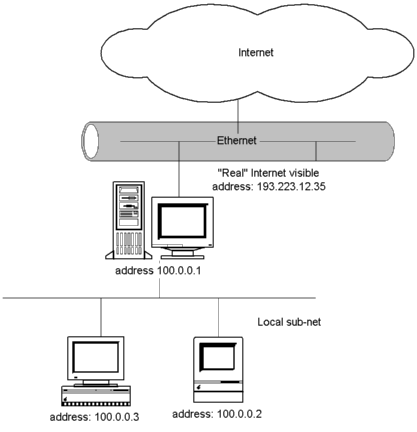
Figure 3.12 ARP-Proxy host with two hosts in local net.
10 Mbps network connection is considered rather slow nowadays. Since bandwidth is shared amongst many hosts in the same segment, a host may have only few hundred Kbps bandwith during office-hours. Switching hubs provide better performance but if LAN backplane is 10Mbps better bandwidth is obtained only locally. Anyhow, world is full of 10Mbps installations and networks - it would be waste of money if they had to be replaced to speed up the LAN.
100Mbps Fast Ethernet utilizes IEEE 802.3 wiring systems, MAC methods and frame formats thus beeing compatible with 10Mbps Ethernet segments. Better performance is gained by improving line encoding and shortening maximum length of the cable. 100Mbps 100BASET twisted pair is similar to 10Mbps 10BASET, only maximum length of the cable is halved to 100 meters. In practice, vast majority of 10BASET installations use less than 100m cable to connect each host to hub [DACO]. Fast Ethernet also utilizes 4 independend wires of ordinary 10BASET cable by providing full duplex operation. In recent installations hubs are usually connected to a switch or router with fiber links where 100Mbps is not a problem.
If single hosts have 100Mbps connections LAN backplane is again the bottleneck. Also, 100Mbps is quite modest speed for high-quality mono mode fiber. To provide speeds needed in high-speed LAN backplane, Gigabit Ethernet Alliance [GIGA] is in process to standardize Gigabit extension to IEEE 802.3.
[GIGA]:
In July, 1996, after months of initial feasibility studies, the
IEEE 802.3 working group created the 802.3z Gigabit Ethernet task force.
The key objectives of the 802.3z Gigabit Ethernet task force are to develop
a Gigabit Ethernet standard that does the following:
Network technologies that would instantly replace Ethernet are not
under development. If ATM has enough potential, ATM Forum LAN Emulation
over ATM or Multi-protocol over ATM migth be competitor for Ethernet.
Worldwide LAN switch market
split by technology, 1995-2001 (Datamonitor, 07/97)
| USD millions |
1995 |
1996 |
1997 |
1998 |
1999 |
2000 |
2001 |
| ATM |
140 |
340 |
650 |
1 020 |
1 340 |
1 700 |
2 000 |
| 10Mbps Ethernet |
1 080 |
2 480 |
3 430 |
4 150 |
4 370 |
4 400 |
4 450 |
| 100Mbps Ethernet |
80 |
240 |
610 |
1 350 |
2 700 |
3 900 |
5 100 |
| Gigabit Ethernet |
0 |
0 |
50 |
200 |
450 |
950 |
1 700 |
| Token ring |
100 |
260 |
450 |
600 |
600 |
550 |
450 |
| IP / L3 switching |
0 |
0 |
60 |
200 |
420 |
800 |
1 150 |
| Other |
100 |
200 |
330 |
400 |
450 |
400 |
350 |
| Total |
1 500 |
3 520 |
5 580 |
7 920 |
10 330 |
12 700 |
15 200 |
LAN Hubs Revenue and Shipments
of Shared Media Hubs to Worldwide (Dataquest 08/97)
|
1997 |
1998 |
1999 |
2000 |
2001 |
CAGR 1997-2001 |
|
| Ports Shipped (K) |
72864,8 |
76563 |
76211,8 |
75030,6 |
73604 |
0,2 % |
| Shipment Growth |
16,1 % |
5,1 % |
-0,4 % |
-1,5 % |
-1,9 % |
|
| Average end-user price (USD) |
66,4 |
55,6 |
48,6 |
46,1 |
46,1 |
-6,9 % |
| End-user revenue (USD M) |
4835,8 |
4258,7 |
3703,4 |
3458,9 |
3390,5 |
-6,7 % |
| Revenue growth |
3,2 % |
-11,9 % |
-13,0 % |
-6,6 % |
-2,0 % |
Worldwide shared media hub market split by technology (Datamonitor, 07/97)
| (USD) |
1995 |
1996 |
1997 |
1998 |
1999 |
2000 |
2001 |
| 10Mbps Ethernet |
3800 |
4020 |
4330 |
4490 |
4580 |
4420 |
4200 |
| 100 Mpbs Ethernet |
240 |
380 |
460 |
540 |
620 |
680 |
700 |
| Token Ring |
730 |
630 |
480 |
350 |
260 |
200 |
150 |
| Other (incl. FDDI) |
180 |
250 |
330 |
390 |
430 |
410 |
350 |
| TOTAL |
4950 |
5280 |
5600 |
5770 |
5890 |
5710 |
5400 |
There are numerous manufacturers of LAN equipment. Especially market of network cards and passive hubs is filled with brands and OEM suppliers. Some better known brands are 3Com, SMC and D-Link for network cards and hubs, Cisco, Bay Networks and former Ipsilon for switches.
Datamonitor report [DATA98] and RFCs have been the main source of this chapter. Each chapter identifies the most relevant references in the opening paragraph.
In the backbone IP can be carried over Frame Relay, ATM, SDH/SONET, PDH, PSTN and WDM networks. Currently ATM, Frame Relay and leased lines are the most popular alternatives. IP over SONET without ATM layers has been mentioned as a more streamlined choice to ATM. WDM is an advanced way to use the huge transmission capacity of optical fibers and its deployment will increase available backbone bandwidth significantly.

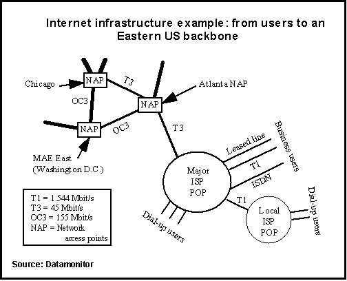
The next figure shows a sample Internet backbone [DATA98]. OCx are SONET links and Tx PCM lines with the bit rates indicated in the figure. A reliable and high capacity (the topics are closely related in a best-effor packet network!) backbone network is central to ISP business in two senses: First, it makes ISP itself an attractive alternative for the customers. Secondly reselling backbone capacity to other (local) ISPs provides a considerable revenue opportunity.
CCITT standardized Frame Relay [I.233] in the early 90's. IETF adopted FR for routing and bridging IP traffic (among others) in "Multiprotocol Interconnect over Frame Relay" [RFC1490].
It is also possible to run "PPP in Frame Relay" [RFC1973]. When Frame Relay is configured as a point-to-point circuit, PPP can use Frame Relay as a framing mechanism, ignoring its other features. This is equivalent to the technique used to carry SNAP headers over Frame Relay [RFC1490]. The two techniques cannot co-exist on the same links. This chapter dicusses the multiprotocol case.
Frame Relay (FR) networks carry variable length packets over PCM links. Its data link layer LAPF is a streamlined version of X.25's LAPB. FR's key distinguishing properties are [STAL98]:
The following figures depict the differences in the intermediate nodes of the network.
Application                                     Application

X.25 - - - - - - - - - -X.25 - - - - - - - - - -X.25

LAPB                    LAPB                    LAPB

PHY                     PHY                     PHY


End node                Routing node            End node
Application                                     Application

TCP/IP                                          TC


P/IP

LAPF - - - - - - - - - -LAPF - - - - - - - - - -LAPF

PHY                     PHY                     PHY


End node                Switching node          End node
Error control at the endpoints only improves performance if error rate is low enough like in todays networks. An order of magnitude speed improvements over X.25 have been reported [HARB92]. Originally FR used speeds up to 2Mbps, but recently also higher rates have become available.
The Frame Relay virtual circuits may form either fully interconnected complete "mesh", or only partially interconnected network where IP-routers pass the packets to next (FR) link. In either case, each virtual circuit is uniquely identified at each Frame Relay interface by a Data Link Connection Identifier (DLCI). In most circumstances, DLCIs have strictly local significance at each Frame Relay interface. The DLCIs are assigned permanently or during FR call setup. It is also possible to negotiate certain FR parameters during the setup.
IP packets may be carried over an FR link using "Multiprotocol Interconnect over Frame Relay" [RFC1490] encapsulation. Maximum frame sizes in FR implementations vary from 262 octects upwards and IETF has specified a simple fragmentation procedure for carrying large frames over a frame relay network with a smaller MTU.
Frame Relay packs the data inside a Q.922 frame [RFC1490]. The format looks as follows:
                  +---------------------------+

                  |    flag (7E hexadecimal)  |

                  +---------------------------+

                  |       Q.922 Address*      |

                  +--                       --+
| |
                  +---------------------------+

                  | Control (UI = 0x03)       |

                  +---------------------------+

                  | Optional Pad      (0x00)  |

                  +---------------------------+

                  | NLPID                     |

                  +---------------------------+

                  |             .             |

                  |             .             |

                  |             .             |

                  |           Data            |

                  |             .             |

                  |             .             |

                  +---------------------------+

                  |   Frame Check Sequence    |

                  +--           .           --+

                  |       (two octets)        |

                  +---------------------------+

                  |   flag (7E hexadecimal)   |

                  +---------------------------+


           * Q.922 addresses, as presently defined, are two octets and

             contain a 10-bit DLCI.  In some networks Q.922 addresses

             may optionally be increased to three or four octets.
The DLCI values are assigned during VC setup. UI means Unnumbered information in HDLC protocols and padding aligns the data to two octet boundary. NLPID tells the receiver which network layer entity should handle the data. ISO 9577 standard defines the value 0xCC to the Internet IP.
There are two basic types of data packets that travel within the Frame Relay network: routed packets and bridged packets. In the former case NLPID identifies a layer 3 entity at the end of FR link. Layer 3 PDU is then encapsulated directly into FR data field. There is also a more complicated encapsulation for protocols which do not have NLPID of their own. IP does have and routed datagrams are as below:
                    Format of Routed IP Datagram

                  +-------------------------------+

                  |        Q.922 Address          |

                  +---------------+---------------+

                  |Control  0x03  |  NLPID  0xCC  |

                  +---------------+---------------+

                  |          IP Datagram          |

                  +-------------------------------+

                  | FCS


|

                  +-------------------------------+
NLPID 0x80 means a Subnetwork Access Protocol (SNAP) follows. A SNAP contains Organizationally Unique Identifier (OUI) and Protocol Identifier (PID). SNAP, MAC addresses and all the media specific fields are needed if FR is used to bridge two LAN segments. Eg. Ethernet encapsulation looks like this:
                   Format of Bridged Ethernet/802.3 Frame

                  +-------------------------------+

                  |        Q.922 Address          |

                  +---------------+---------------+

                  |Control  0x03  | pad     0x00  |

                  +---------------+---------------+

                  | NLPID   0x80  | OUI     0x00  |

                  +---------------+             --+

                  | OUI  0x80-C2                  |

                  +-------------------------------+

                  | PID 0x00-01 or 0x00-07        |

                  +-------------------------------+

                  | MAC destination address       |

                  :


;    :

                  |


;    |

                  +-------------------------------+

                  | (remainder of MAC frame)      |

                  +-------------------------------+

                  | LAN FCS (if PID is 0x00-01)   |

                  +-------------------------------+

                  | FCS


|

                  +-------------------------------+
PID value 0x00-0D means FR level fragmenting on the link. It is needed because of the FR's small default maximum packet size. The default IP operation is to fragment datagrams at routers if needed and reassemble at the final destination [RFC0791]. A link with small maximum packet size can ruin the performance of the entire connection. FR level fragmenting hides the actual frame size from IP layers at the link endpoints. The whole thing looks quite like IP level fragmenting and is not investigated in detail here.
I-Series Recommendations of ITU-T standardize B-ISDN and ATM. ATM Forum and IETF have added several upper level protocols to take advantage of the high bit rates available. "IP over ATM: A Framework Document" [RFC1932] and "Multiprotocol Encapsulation over ATM Adaptation Layer 5" [RFC1483] lay common basis for both organizations.
ATM is a cell-switching technology with both LAN and WAN applications. It uses a fixed 53-byte cell format. ATM has been developed to ensure efficient transmission of voice, video and data traffic over the same network. ATM offers transmission speeds of 25 Mbit/s, 155 Mbit/s and 622 Mbit/s, and OC48 products will be shipped in 1998.
According to Datamonitor ATM is gaining market share from Frame Relay as an ISP backbone technology. Currently the shares are about equal but ATM is growing twice as fast.
IP over ATM uses RFC-1483 encapsulation to carry IP packets over ATM. The traditional way of segmenting packets at the IP layer does not work with ATM due to the tiny cell size. Instead AAL5 segments and reassembles the packets and provides at least 8k MTU to the IP layer.
IETF and ATM Forum have standardized virtual LAN technologies to be used with ATM. There are already products for single VLAN subnets but connecting these nets across ATM in the most cost effective way is still under research. Another presentation [IPOA98] in this seminar goes into details.
SONET and SDH are the standard ways to connect optical fiber based transmission systems. SONET is ANSI standard used in North America and SDH ITU-T Recommendation for the rest of the world. IETF defines use of SONET in "PPP over SONET/SDH" [RFC1619].
PPP treats SONET/SDH transport as octet oriented synchronous links. PPP packets are encapsulated in the "Octet synchronous HDLC" way of [RFC1549]. The data is not scrambled which may cause cause operational problems in SONET networks [MANC97]. A user may gain control of SONET synchronous payload envelope (SPE) and lower line performance, cause loss of signal or loss of frame failures. ANSI and ITU-T standards are being updated to include HDLC to SONET and SDH mappings. [NART98] suggests using these new mappings and changing RFC-1619 to "Historic".
In conjunction with the deployment of fibre optic transmission media, some ISPs are beginning to turn to Wavelength Division Multiplexing (WDM) [DATA98]. In contrast to other multiplexing techniques such as TDM and FDM, WDM works by modulating data streams onto different parts of the light spectrum and has been specifically developed to optimise multiplexing over fibre infrastructures. WDM is expected to become the most prevalent multiplexing technology across ISP backbones.
HDLC framing of PPP over SONET uses byte stuffing to achieve data transparency. The mechanism is simple and practical in almost any environment (HDLC's other transparency scheme, bit stuffing, is virtually impossible without dedicated hardware). However, byte stuffing has its limits when transmission speed increases since each and every octet has to be checked. Scaling above 2.5 Gb/s (OC-48) needs other yet unspecified mechanisms. This means there has to be a terminal multiplexer at the end of WDM system with output ports at or below OC-48.
Differentiated Services mean adding priority classes to IP packets. The priorities enhance the service delay sensitive applications get. Diffserv implementation takes into use the TOS bits of IPv4 header which are mostly ignored in current routers. IP switching schemes [IPOA98] use switched shortcut paths to minimize the delay - but switching means state oriented datagram forwarding which is against IP principles. Diffserv is a pure connectionless and stateless approach. Inside each priority class Diffserv is still best-effort forwarding which means severe backbone overload may increase the delay to unacceptable level even for the highest priority datagrams.
Interested readers may find more information from the following places:
The following market forecast expects ATM to grow twice as fast as Frame Relay in the near future. However, the forecast is almost year old now and ATM's position is not considered as strong any more.
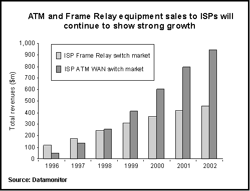
IP over SONET or WDM are currently the hot topics in backbone router forecasts. [HATA98] provides data on today's existing routers and vendors.
| AAA |
Authentication, Authorization and Accounting |
| ADSL | Asymmetric Digital Subscriber Line |
| ATM | Asynchronous Transfer Mode |
| CCB | Customer Care and Billing |
| CHAP | Challenge-Handshake Authentication Protocol |
| CPE | Customer Premises Equipment |
| DSLAM | Digital Subscriber Line Access Multiplexer |
| DTM | Dynamic Time-Division Multiplexing |
| FDDI | Fiber Distributed Data Interface |
| GSM | Global System for Mobile Communications |
| IP | Internet Protocol |
| ISDN | Integrated Services Digital Network |
| ISP | Internet Service Provider |
| L2TP | Layer 2 Tunneling Protocol |
| LAN | Local Area Network |
| LCP | Link Control Protocol |
| NCP | Network Control Protocol |
| NMS | Network Management System |
| NT | Network Terminal |
| OSI | Open Systems Interconnection |
| PAP | Password Authentication Protocol |
| PC | Personal Computer |
| PDH | Plesiochronous Digital Hierarchy |
| POTS | Plain Old Telephone Service |
| PPP | Point-to-Point Protocol |
| PSTN | Public Switched Telephone Network |
| RADIUS | Remote Authentication Dial In User Service |
| RAN | Remote Access Node |
| SDH | Synchronous Digital Hierarchy |
| SLIP | Serial Line IP |
| SOHO | Small Office Home Office |
| SONET | Synchronous Optical Network |
| UMTS | Universal Mobile Telephone System |
| WDM | Wavelength Division Multiplexing |
[DCAP]
Fred Halsall. Data Communications, Computer Networks and Open Systems, Fourth Edition. Addison-Wesley Publishing Company, 1996.
[LMAN]
William Stallings. Local & Metropolitan Area Networks, Fifth Edition. Prentice-Hall, Inc, 1997.
[BRSW]
Bay Networks. Routing Switch Technology - White Paper. <HTTP://business5.baynetworks.com/CatalogRelatedDocs.asp>
[GIGA] Gigabit Ethernet Alliance. <HTTP://www.gigabit-ethernet.org/>
| Layer Two Tunneling Protocol "L2TP" | http://search.ietf.org/internet-drafts/draft-ietf-pppext-l2tp-11.txt |