2. OVERVIEW OF ATM SWITCH
In the ATM switch, the ATM cells have to be transported from an inlet to one or
more outlets. This switching from inlet to outlet can be combined with
concentration/multiplexing and expansion/demultiplexing of the ATM traffic. In
most switching architectures, all functions are available in one or another
combination. In principle, an ATM switch shall perform the following two basic
functions: switching and queuing.
Switching functions: the transportation of information from an incoming logical
ATM channel to an outgoing logical ATM channel, to be selected between a number
of outgoing logical channels. This logical ATM channel is characterized by:
- A physical inlet/outlet, characterized by a physical port number.
- A logical channel on the physical port, characterized by a virtual channel
identifier (VCI) and/or virtual path identifier (VPI).
To provide the switching function, both the inlet and incoming virtual
channel/path identifier have to be related to the outlet and outgoing virtual
channel/path identifier. Two functions have to be implemented in an ATM
switching system: space and time switching functions. The space switching
function means that information from inlet i is transported to outlet j, and
the time switching function means that information of time slot i is switched
to time slot j. However, in ATM switching systems, the time identification is
replaced by a logical channel identification.
Queuing functions: Since the pre-assigned time slot concept disappears in
ATM switching systems, a contention problem arises if two or more logical
channels contend for the same time slot. This can be solved by queuing, another
important aspect of ATM switching systems. The way these functions are
implemented and where in the switch these functions are located, will
discriminate one switching solution from another.
The following sections will briefly describe a number of alternative switching
architecture proposals and buffer strategy.
2.1. Classification of Space Division ATM Switch
In literature the switches have been mainly classified into two classes: time
division switch and space division [Ahm89, Tob90, New92]. Since this thesis
only involves the space division switches, in the following section only the
space division switches are discussed. A simple classification of a space
switch fabric that includes most of the proposed approaches is illustrated in
figure 1. Interconnection networks for a space division switch fabric may be
divided into four basic classes: crossbar-based fabric, banyan based network,
sort Batcher network, and fabric with disjoint path topology. The four classes'
switches are a single-path network that have a unique path through the
interconnection network between any given input and output pair. To improve
throughput of the single path networks, the multiple-path networks offer a
number of different paths available between any input and output, and can be
evolved from the above four classes by providing dilated links, parallel
networks, augment networks, Clos' connections and a recirculating network.
2.1.1. Single-path networks
Crossbar based fabric: Crossbar switches have always been attractive to
switch designers because they are internally nonblocking and they are simple. A
major issue in such switches is where to place the queuing function (i.e.,
input buffer, output buffer, or crosspoint buffer) [Noj87, Tob90]
to resolve output blocking. Crossbar designs have a complexity in paths or
crosspoints that grows as a function of
 where N is the number of input ports or output ports for the ATM switch.
Thus, they do not scale well to large sizes. They are however very useful for
the construction of nonblocking, self-routing, switching elements and switches
of modest size.
where N is the number of input ports or output ports for the ATM switch.
Thus, they do not scale well to large sizes. They are however very useful for
the construction of nonblocking, self-routing, switching elements and switches
of modest size.
Banyan network: The banyan network [Gok73] covers a large class of
interconnection networks that has only a single path between any input and
output. A number of specific topologies [Dai81b, 84, Pat79, 81] belong to the
banyan family, but all offer an equivalent performance for random traffic. The
banyan network has a complexity of paths and switching elements of the order
 .
This makes it much more suitable than the crossbar structures for the
construction of large switch fabrics. Unfortunately, the banyan is an internal
blocking network and its performance degrades rapidly as the size of the
network increases. There are several ways to reduce the internal blocking to a
level that is acceptable for ATM:
.
This makes it much more suitable than the crossbar structures for the
construction of large switch fabrics. Unfortunately, the banyan is an internal
blocking network and its performance degrades rapidly as the size of the
network increases. There are several ways to reduce the internal blocking to a
level that is acceptable for ATM:
provide buffers in every basic switching node internally in the switching
fabric (i.e., buffered banyan) [Dai81a, Tur85, Hub88],
use a back-pressure mechanism between the switching nodes, to delay the
transfer of blocked cells. An example is the cut-through
network[Ker79],
use multiple networks in parallel to provide multiple paths between
input and output,
provide multiple links internally between the switching nodes (dilated
network),
add extra stages of a banyan or delta network to introduce multiple paths
(augment network).
Methods (3), (4) and (5) will be introduced in the following.
Batcher-banyan network: Another method to overcome the inherent internal
blocking in banyan networks is to use the Batcher network [Bat68] which
offers an attractive solution. The combiation of the Batcher and the banyan
network will offer a nonblocking performance if some means is provided to
prevent multiple cells simultaneously requesting the same destination. An
implementation of this technique is the Starlite switch [Hua84, Hua86]
which uses a trap network between Batcher sort and the banyan that detects
cells with equal destination addresses at the output of sort. Thus, the cells
with repeated addresses are separated from the ones with distinct addresses and
are fed back to the input side of the sort network for re-entry within the next
cycle. These cells can only use the idle input ports. Since the number of
recycled cells at any time can be larger than the free input ports, a buffering
stage must be used for the recycled cells if packet loss is not acceptable. The
switch described in [Hui87] uses this type of fabric also, and employs a
three-phases' algorithm to resolve output contention. The drawback in
this switch is that it uses input queuing which restricts its throughput due to
the head-of-line (HOL) blocking phenomenon. The designs of the Sunshine
switch [Gia91] and the Self-Routing Growable Packet Switch
(Self-routing GPS) [Eng91] are such that multiple banyan networks, say
K, are used in parallel to route K cells to the same output, thus
the excess cells will be discarded (Self-routing GPS) and recirculated
into input entries (Sunshine). However, achieving the Batcher
network becomes increasingly more difficult for larger switching sizes, because
the Batcher network is a synchronous network and requires that all cells are
aligned on a common boundary at each column of switching elements. In addition,
the growth of a Batcher network is of the order of
 ,
so many more switching stages are required in the Batcher network than in the
banyan network. A modular nonblocking switch architecture proposed by Lee
[Lee90] is configured in two stages, the first-stage consists of
Batcher-banyan switch modules of dimensions
,
so many more switching stages are required in the Batcher network than in the
banyan network. A modular nonblocking switch architecture proposed by Lee
[Lee90] is configured in two stages, the first-stage consists of
Batcher-banyan switch modules of dimensions
 ,
the second-stage switch modules are statistical multiplexers of dimensions
,
the second-stage switch modules are statistical multiplexers of dimensions
 .
The two-stage Buffered Nonblocking Switch (BNS) proposed in publication
4 also uses the Batcher-banyan network in each stage. The aim of this switch is
to construct a large size switch and to reduce switching complexity. The whole
.
The two-stage Buffered Nonblocking Switch (BNS) proposed in publication
4 also uses the Batcher-banyan network in each stage. The aim of this switch is
to construct a large size switch and to reduce switching complexity. The whole
 switch is divided into two stages and each stage has several
 or
or
 (where N=
 )
small size switches which are simplified Sunshine switches having theirs own
output buffers.
)
small size switches which are simplified Sunshine switches having theirs own
output buffers.
Fabrics with disjoint paths' topology and output queuing: Fabrics with
disjoint path topologies use a full connection network topology to connect each
input to each output. Output queuing is used to resolve output contention and
it offers an improved throughput performance. A classic example of this
architecture is the Knockout Switch [Yen87]. An important
contribution of this architecture is the philosophy that by permitting small
percentages of cell losses, the number of queuing buffers can be reduced
substantially. Because cell losses occur anyway due to errors in communication
links, introducing losses of this magnitude or less is essentially unnoticed in
terms of end-to-end reliability. The Knockout Switch takes
advantage of the fact that an output buffer scheme provides the best
delay/throughput performance [Hlu88] and that, with uncorrelated traffic among
input ports and uniformly directed to all output ports, the probability of more
than L (e.g., 8) cells destined for any particular output port in each
cell time slot is very low (e.g.,
 ).
Under these conditions, the number of cell filters and the hardware complexity
of the concentrator are about O(N) instated of O(
).
Under these conditions, the number of cell filters and the hardware complexity
of the concentrator are about O(N) instated of O(
 ).
However, the number of interconnection wires in the crossbar-link network is on
the order of O(
).
However, the number of interconnection wires in the crossbar-link network is on
the order of O(
 ).
A way to reduce the number of wires is to use L instead of N
routing links for each output port, as the so called distributed
Knockout Switch (distributed KS) [Cha90, Cha91]. The cell
filtering and concentration functions are processed distributedly in small
switch elements located at the intersection of the crossbar lines. To reduce
the value of the parameter L in the Knockout Switch, and
M/1-stage switch [Kil90] provides an input and output buffers,
but it requires a larger number of buffers.
).
A way to reduce the number of wires is to use L instead of N
routing links for each output port, as the so called distributed
Knockout Switch (distributed KS) [Cha90, Cha91]. The cell
filtering and concentration functions are processed distributedly in small
switch elements located at the intersection of the crossbar lines. To reduce
the value of the parameter L in the Knockout Switch, and
M/1-stage switch [Kil90] provides an input and output buffers,
but it requires a larger number of buffers.
Another switch fabric, the design of which is based on an interconnection
structure with no internal blocking and queuing capacity at the outputs, is the
Integrated Switch Fabric (ISF) proposed in [Ahm88]. This switch
fabric is designed to handle both circuit-switched and packet-switched traffic
in a unified manner. It uses a binary tree to route the packet at every input
to the appropriate bin. Here, however, the bins are shift registers of a size
equal to only one packet. In every slot, the contents of all N registers
corresponding to a given output line are emptied sequentially into a FIFO
buffer; this is the concentration function which is accomplished by a
multiplexer running at a speed N times that of an input line. This
fabric requires
 paths. By interleaving the distribution and concentration stages, the
Christmas Tree switch uses less than
paths. By interleaving the distribution and concentration stages, the
Christmas Tree switch uses less than
 paths [Wan91].
2.1.2. Multiple-path networks
Multiple-path networks are used to improve the performance of a single-path
network. Since multiple paths are available between every input-output pair, an
algorithm is required to select one of the paths.
Dilated banyan: To provide multiple links internally between the switching
nodes, a dilated network replaces each link of the simple banyan networks by
K parallel links [Kum83, Gho91, Wid91, Lie90 and Lee92]. This option may
cause out-of-sequence arrival at the output of the switching fabric,
introducing the need for a resequencing means at the output of the switching
fabric.
Multiple networks in parallel: Another approach to introducing multiple
paths into an interconnection network is to connect multiple switch planes in
parallel. This approach offers both increased reliability and improved
performance. The multiple banyan networks (say K) may be used in
parallel [Kum83]. The input load is then divided among the K banyan
networks, thus reducing the load on each and improving the overall success
rate. At the output, cells are merged into output buffers. Clearly, the
throughput of the fabric improves with increasing K. The Parallel
Delta Network (PDN) [Ber88,89] identified by mixing
parallel networks and augmented networks provides the minimum number of Delta
subnetworks in parallel that provide rearrangeability property. The
Sunshine, Self-routing GPS, and SCOQ [Che91a] offer
multiple banyan networks to provide multiple paths which allow multiple cells
to compete for the same destination. They also belong to the Batcher-banyan
network category and require an
Batcher network. To construct a large switch, the MULTIPAR [1, 2] switch
achieves a two-stage modular fabric, providing multiple complete parallel
switching planes in the second stage, and constructs memoryless first-stage
switching modules. Each switching module is achieved by small Batcher and
multiple banyan networks and they can be asynchronous among the switching
modules.
Augment network: Multiple paths may be introduced into a banyan or delta
network by adding extra stages of switching elements. The number of paths
between each input and output port is doubled for each extra stage added to the
banyan network. The extra stage can be used to distribute the traffic evenly
across the banyan (or delta) network, to remove the sensitivity of the network
to the incident traffic pattern, and to improve the network's performance. An
example is a tandem of a distribution network and a routing network
(DN+RN) [Tur85, 86, Bub86, Bub89, Kim91b]. If (logN-1)
stages are added to a banyan network, the Bense network [Ben64]
results in a nonblocking interconnection. The Bense network is known to
be the smallest interconnection network for which all permutation patterns are
realizable. The algorithm required to set the N paths in the network for
a given permutation, however, is not distributed as in the self-routing
procedure, but rather requires global knowledge of all requests. By introducing
the distributors between stages of switching elements, the cells can be evenly
distributed to all the input ports of switching elements in the next stages.
The switch having output buffers in each stage (Decomposition) [Kim90,
91a] has self-routing property and achieves the maximum throughput of 100% only
with a speed-up factor of two. An alternative to using the additional stages to
distribute the traffic across the input ports of the banyan routing stage is to
use all the stages as routing stages. Cells are removed from the network at the
earliest possible switch stage. Conflicts between cells requesting the same
link are handled by deflecting one of the cells over the wrong link and making
it recommence its routing from the resulting location. Provided there are
sufficient remaining switching stages in the network the cell may still arrive
at the required output. The opportunity to remove cells can be given after
every stage (Fold Shuffle [Cam91] or Shuffleout I
[Dec91a] ), after the first logN stages (Rerouting) [Uru90,
91], or after each complete banyan network if multiple banyan networks are
connected in series (Tandem I) [Tob91].
Clos network: A Clos' network [Clo53] constructed with nonblocking
switch modules will have m paths between each input-output pair and will
be strictly nonblocking if m>2n-1 where n is the number of
inputs per individual switch in the first stage, and m is the number of
individual swathes in the second stage. If
 ,
a rearrangeable nonblocking network can be constructed. The rearrangeable
nonblocking Clos network is especially attractive because it can be
realized with less hardware than a nonblocking network. As rearrangeable
nonblocking multistage switching networks, a path establishment algorithm is
normally required. A Multistage Alternate Routing Switch (MARS)
[Deg89] is constructed in the Clos' interconnection which provides
multiple paths to reduce the likelihood of collisions and increases the
throughput of the fabric. A switch in each stage implements a nonblocking
switch which is the Benes network that contains its own buffers. The
Generalized Knockout Switch's multistage configuration (Generalized
KS), i.e., Growable Packet Switch, is based on the Clos
structure [Eng89, Kar89]. It consists of two parts; one is the
Interconnection network fabric of
,
a rearrangeable nonblocking network can be constructed. The rearrangeable
nonblocking Clos network is especially attractive because it can be
realized with less hardware than a nonblocking network. As rearrangeable
nonblocking multistage switching networks, a path establishment algorithm is
normally required. A Multistage Alternate Routing Switch (MARS)
[Deg89] is constructed in the Clos' interconnection which provides
multiple paths to reduce the likelihood of collisions and increases the
throughput of the fabric. A switch in each stage implements a nonblocking
switch which is the Benes network that contains its own buffers. The
Generalized Knockout Switch's multistage configuration (Generalized
KS), i.e., Growable Packet Switch, is based on the Clos
structure [Eng89, Kar89]. It consists of two parts; one is the
Interconnection network fabric of
 ,
the other is output packet modules of
,
the other is output packet modules of
 .
An important contribution of the Generalized KS is that the parameter
m (m<<N, the number of simultaneous cells destined
to a group output), is independent of N and is large enough to keep cell
loss probability below all other cell loss probabilities (e.g., buffer
overflow, link failure, etc.). The interconnection network fabric is a
memoryless two stage interconnection and its function is only to transport up
to m cells to each output module and drop the excessive cells destined
to the same output module in each slot with a path assignment controller. The
Generalized KS takes advantage of the fact that an output buffer scheme
provides the best delay/throughput performance. The three-stage Clos'
structure provides small switching complexity and growability of the switch;
however, it requires a global knowledge of all cell requirements for path
assignment. The path assignment in the Clos' switch normally
requires a computing time dependent of a function of N number of
input/output ports. This processing speed is not fast enough for fast
packet switching when N is large. To solve this problem, we propose to
use a neural network path establishment algorithm instead of a conventional
algorithm. Some examples of this neural network application have been shown in
publications 7, 8 and 9. The most attractive advantage of the neural network
path assignment algorithm is that the convergent time of this neural network
algorithm is independent of switch size.
.
An important contribution of the Generalized KS is that the parameter
m (m<<N, the number of simultaneous cells destined
to a group output), is independent of N and is large enough to keep cell
loss probability below all other cell loss probabilities (e.g., buffer
overflow, link failure, etc.). The interconnection network fabric is a
memoryless two stage interconnection and its function is only to transport up
to m cells to each output module and drop the excessive cells destined
to the same output module in each slot with a path assignment controller. The
Generalized KS takes advantage of the fact that an output buffer scheme
provides the best delay/throughput performance. The three-stage Clos'
structure provides small switching complexity and growability of the switch;
however, it requires a global knowledge of all cell requirements for path
assignment. The path assignment in the Clos' switch normally
requires a computing time dependent of a function of N number of
input/output ports. This processing speed is not fast enough for fast
packet switching when N is large. To solve this problem, we propose to
use a neural network path establishment algorithm instead of a conventional
algorithm. Some examples of this neural network application have been shown in
publications 7, 8 and 9. The most attractive advantage of the neural network
path assignment algorithm is that the convergent time of this neural network
algorithm is independent of switch size.
Recirculating Networks: The networks recirculate cells that have failed to
reach the required output. The Sunshine switch and
Starlite switch belong to this category. Other designs (Tandem
II [Tob91] and Shuffleout II [Dec91b] ) permit cells to exit from
the network's internal stages.
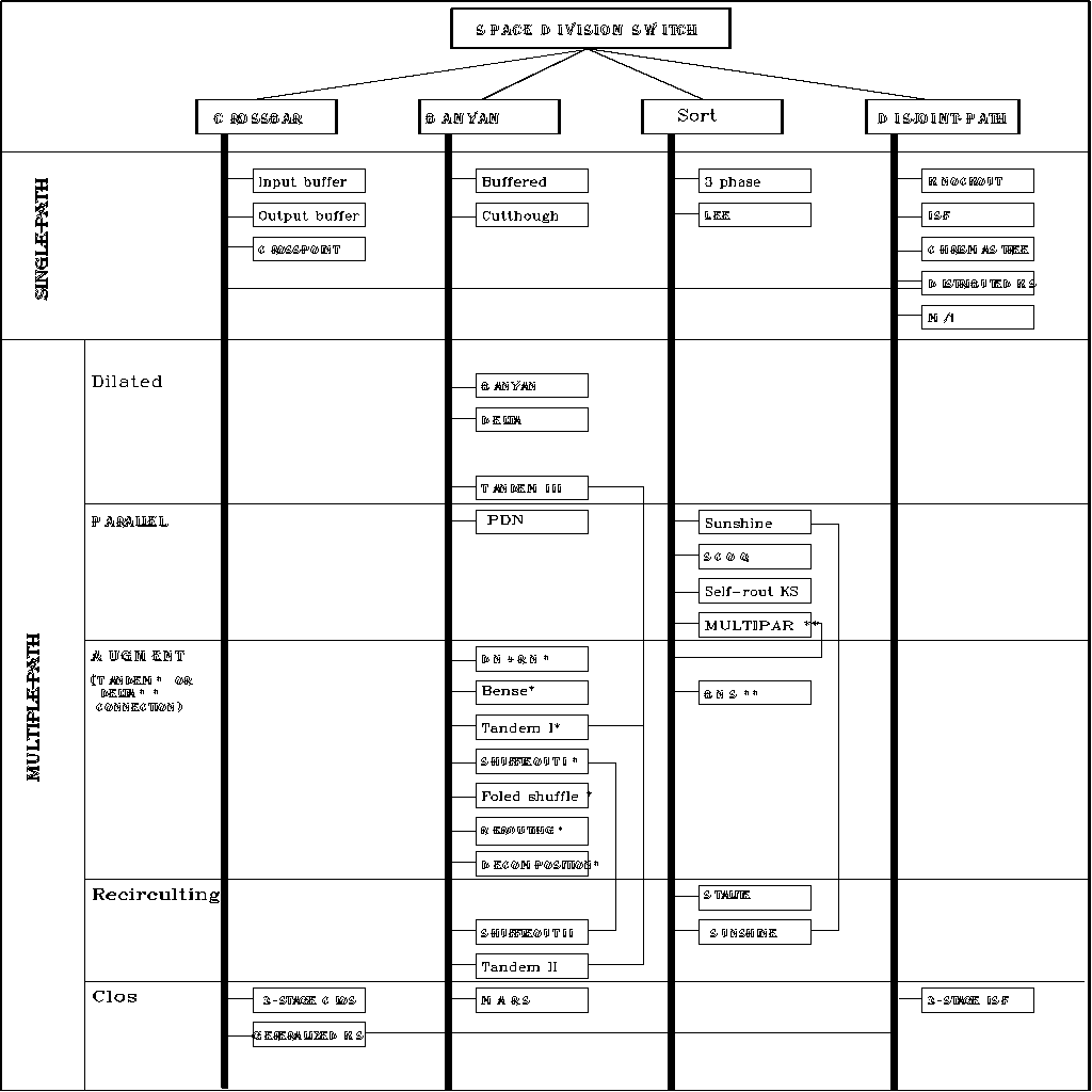
Fig. 1 Classification of space division ATM switching fabric
2.2. Evolution of ATM Switch Topology
There has been an enormous effort on the design, analysis and prototyping of
ATM switches. Up to now, however, the switches implemented have been fairly
small (e.g., 3232 and 6464). To make broadband communications truly accessible
to individual users, it is estimated that a BISDN central office will need to
provide more than 10,000 connections. We therefore have a need to study ways to
interconnect small switches to form a very large scale switch fabric.
In this section, an evolution of ATM switch topology is introduced and from
this point of view we can learn the way of the growability of switches. Since
we are interested in differences between switching fabrics rather than details
of implementation, we will consider switches based on low-level architecture
choices. Figure 2 including several broad categories of switches illustrates
the evolution. These switch architectures can be evolved from one to another by
increasing/reducing dilated links or switching element size. Note that these
objectives are somewhat in conflict with one another. Given a target switch
fabric size, we need to increase the number of switches and the number of
interconnections' lines if we want to reduce the switch size. To achieve a low
cell loss probability, multiple alternative paths within the switch fabric need
to be provided. However, this increases the number of interconnection lines and
requires sophisticated algorithms to preserve the cell output sequence. Most of
the switch interconnection architecture is either a two-stage or a three-stage
architecture.
First we consider a generic two-stage interconnection as shown in figure 2. The
first-stage consists of k switches of dimension
 and the second-stage consists of l switches of dimension
 .
Since several cells at the input of a first-stage switch may addresses the same
second-stage switch, it is necessary to provide buffers at the output of the
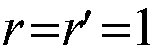
first-stage switch. If the number of r lines is not enough to keep a
required switching performance, for instance, if r=1, this
network becomes a delta network (publication 4), or to provide more than
one line, say r lines, for each path between the two stages, for
instance an input/output dilated delta network. In the case of N
and r are large, the size of second stage switches would be not scaled.
To reduce the size of second stage switches, the second stage switches may be
partitioned into r parallel planes each of which is composed of small
size switching elements (MULTIPAR switch). In the other branch of
the figure, the Knockout Switch, the Lee' switch, and the
Christmas tree switch can be evolved from a delta network
by increasing the number of second stage switches and/or the number of first
stage switching switches.
.
Since several cells at the input of a first-stage switch may addresses the same
second-stage switch, it is necessary to provide buffers at the output of the
first-stage switch. If the number of r lines is not enough to keep a
required switching performance, for instance, if r=1, this
network becomes a delta network (publication 4), or to provide more than
one line, say r lines, for each path between the two stages, for
instance an input/output dilated delta network. In the case of N
and r are large, the size of second stage switches would be not scaled.
To reduce the size of second stage switches, the second stage switches may be
partitioned into r parallel planes each of which is composed of small
size switching elements (MULTIPAR switch). In the other branch of
the figure, the Knockout Switch, the Lee' switch, and the
Christmas tree switch can be evolved from a delta network
by increasing the number of second stage switches and/or the number of first
stage switching switches.
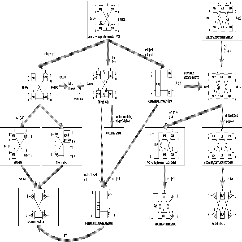
Figure 2 Evolution of ATM switch topology
Second we consider a generic three-stage interconnection as shown in the same
figure 2. The Clos' switch [Clo53]or the Growable Packet
Switch (GPS) [Eng89, Kar89] can be evolved from the generic
three-stage interconnection by setting
 .
It has been shown by Clos that a strict-sense nonblocking Clos'
switch is achieved when
.
It has been shown by Clos that a strict-sense nonblocking Clos'
switch is achieved when
 ,
where n is the number of inputs per individual switch in the first
stage, and q is the number of individual swithes in second stage, and
n and q are defined as in figure 2. The Clos also represents a
rearrangeable nonblocking Clos' switch when
,
where n is the number of inputs per individual switch in the first
stage, and q is the number of individual swithes in second stage, and
n and q are defined as in figure 2. The Clos also represents a
rearrangeable nonblocking Clos' switch when
 .
The rearrangeable nonlblocking Clos' switch has the fewest number
of crosspoints in these nonblocking switches. This Clos-type fabric was found
to be economically feasible and thus many present-day space switch fabric
designs contain Clos-type switching fabrics. In ATM switch design, the
GPS used the Clos-type fabric to achieve a high performance
output queuing switch by choosing a parameter q>n, for example
when n=16, and q=33 it is large enough to keep the cell
loss probability below
.
The rearrangeable nonlblocking Clos' switch has the fewest number
of crosspoints in these nonblocking switches. This Clos-type fabric was found
to be economically feasible and thus many present-day space switch fabric
designs contain Clos-type switching fabrics. In ATM switch design, the
GPS used the Clos-type fabric to achieve a high performance
output queuing switch by choosing a parameter q>n, for example
when n=16, and q=33 it is large enough to keep the cell
loss probability below
 for a 90% load. The parallel network is a special case of the Clos
network when the number of first and third switch increase and reach N.
In this branch of the category, the path assignment algorithm is normally
required. In this three-stage interconnection fabric, the simplified
Sunshine switch (Sunshine switch without
recirculating buffering) [Eng91] can be evolved from the self-routing GPS
by increasing the number of third switches. The difference between the
simplified Sunshine switch and self-routing GPS is only
that the function of the first two stage's switches respectively is to
transport up to q cells to each output group module in the
self-routing GPS or to each distinct output in the simplified
Sunshine switch.
for a 90% load. The parallel network is a special case of the Clos
network when the number of first and third switch increase and reach N.
In this branch of the category, the path assignment algorithm is normally
required. In this three-stage interconnection fabric, the simplified
Sunshine switch (Sunshine switch without
recirculating buffering) [Eng91] can be evolved from the self-routing GPS
by increasing the number of third switches. The difference between the
simplified Sunshine switch and self-routing GPS is only
that the function of the first two stage's switches respectively is to
transport up to q cells to each output group module in the
self-routing GPS or to each distinct output in the simplified
Sunshine switch.
2.3. Queuing
Queuing is the primary factor determining the performance of a switch. The
queuing can be simply classified into four catagorries (see Figure 3). These
are determined by the physical location of the queues: at the inputs, the
outputs, inputs and outputs, or shared queuing.
Input queuing: In this input queuing solution the approach is taken to
solve the possible contention problem at the input. Between the input queues
and the switch fabric, arbitration logic has to be employed which decides which
input port to serve. The switch fabric will then transfer the cell from the
input queues to the output port without internal contention. This approach
suffers from the so-called Head of Line (HOL) blocking, which has a throughput
of only about 58 percent for a large nonblocking switch with first-in-first-out
input queues, saturated with uniform random traffic. This approach permits the
input queues to be located separately from the switch fabric, simplifies the
implementation of the switch fabric, and avoids the need for queues operating
at some multiple of the port speed. Input queuing switches are found in
references [Hui87, Lea90, Mat91, Oie90, Ma91, 92] and publication 7.
Output queuing: In this output queuing solution, every output port must be
able to accept cells from every input port simultaneously during one time slot.
However, only a single cell may be served by an output port, thus causing
possible output contetion. The possible output contetion is solved by queues
which are located at each output of the switch fabric and allow it to store
multiple cells which may arrive during one time slot. In ideal output queues,
all input ports can simultaneously have a cell destined to a single output
port. To ensure that no cell is lost in the switch fabric before it arrives at
the output queue, the cell transfer must be performed at N times the
speed of the input ports. The system must be able to write N cells in
the queues during one time slot. However, for the large switch, it is
unreasonable to expect the switch fabric and output buffers to have sufficient
capacity to achieve the ideal output queuing operation. However, to ensure that
the cell loss probability is sufficiently low for all reasonable patterns of
incident traffic and acceptable operating loads, each output queue can receive
up to a certain number, say L<<N, instead of N. For
instance, if each output queue can receive up to eight cells within any single
time slot, a cell loss probability of less than
 may be achieved for a traffic load of 90 percent with uniform random traffic.
The output queuing switch achieves the optimal throughput-delay performance
[Hlu88], however it can be much more complex than an input queuing switch
because the switch fabric and output queue must efficiently operate at a much
higher speed than that of each switch port to reduce the probability of cell
loss. The switch with a dedicated output port has separate queues on each
output port, each of queues shared by all input ports wishing to access that
output port. The IFS Knockout, GPS, Self-routing GPS,
Distributed KS, Tandem I, Shuffleout I, Christmas Tree, SCOQ and MULTIPAR
switches [Ahm88, Yen87, Cha91, Eng91, Tob91, Dec91a, Wan91, Che91a, and
publications 1, 2] are typical output queuing switches. The switch in
publication 4 has separate output queues in each stage.
may be achieved for a traffic load of 90 percent with uniform random traffic.
The output queuing switch achieves the optimal throughput-delay performance
[Hlu88], however it can be much more complex than an input queuing switch
because the switch fabric and output queue must efficiently operate at a much
higher speed than that of each switch port to reduce the probability of cell
loss. The switch with a dedicated output port has separate queues on each
output port, each of queues shared by all input ports wishing to access that
output port. The IFS Knockout, GPS, Self-routing GPS,
Distributed KS, Tandem I, Shuffleout I, Christmas Tree, SCOQ and MULTIPAR
switches [Ahm88, Yen87, Cha91, Eng91, Tob91, Dec91a, Wan91, Che91a, and
publications 1, 2] are typical output queuing switches. The switch in
publication 4 has separate output queues in each stage.
Input and output queuing: In order to reduce the high operation speed of
the output queuing switch, i.e., the value of L must be reduced, some
architecture can be constructed utilizing a combination of both input queuing
and output queuing. In this case, the switch fabric only requires a lower value
of L than one in the output buffering switch. Since cell loss within the
switch fabric of an output queuing switch due to transient traffic patterns is
undesirable, instead of discarding cells that cannot be handled during the
current time slot, they are retained in input queues. The input queues need not
be large to substantially reduce the probability of cell loss for reasonably
random traffic, even at very high loads. This is an approach favored by a
number of large switch designs [New88, Patt90], for example, Folded Shuffle,
Lee' switch [Cam91, Lee90] and the switch proposed in publications 8 and
9.
Shared queuing: The shared buffer approach still provides for output
queuing, but rather than have a separate queue for each output, all memory is
pooled into one completely shared queue [Dev88, Koz91, Sho91]. The shared queue
approach requires fewer queues than output queuing, because several separate
queues are combined in a single memory. A more complicated control logic is
required to ensure that the single memory performs the FIFO discipline to all
output ports. The Starlite, Sunshine, Tandem II, and Shuffleout
II switches [Hua84, Gia91, Tob91, Dec91b] employ recirculation queues which
may be classified into the shared queue approach. In those switches the output
port condition is handled by recirculating those cells that cannot be output
during current time slot, back to the input ports via a set of recalculation
queues. The recirculation may cause out-of-sequence errors between cells in the
same virtual connection unless steps are taken to prevent it.
Figure 3 Queue allocation strategies